Space-Based Architecture Style
The space-based architecture style is crafted to tackle challenges related to high scalability, elasticity, and concurrent user demands. It proves beneficial for applications dealing with variable and unpredictable concurrent user volumes. Architecturally addressing extreme scalability issues is often more effective than attempting to scale out a database or retrofit caching technologies into a non-scalable architecture.
In high-volume applications with significant concurrent user loads, the database typically becomes the ultimate bottleneck, limiting the number of transactions processed concurrently. Despite the assistance of various caching technologies and database scaling products, scaling out a conventional application for extreme loads remains a challenging task.
Web-Based Bussiness
In web-based businesses, the usual flow involves a request from a browser hitting the web server, then an application server, and finally, the database server. This works well for a small user group, but as users increase, bottlenecks emerge at each layer—first at the web server, then the application server, and finally, the database server. Scaling out web servers is a common response, but it often shifts the bottleneck to the application server, which is more complex and costly to scale. Even if the database is scaled (and even more costly to scale), the result is a triangle-shaped topology, with web servers being the easiest to scale and the database the hardest.
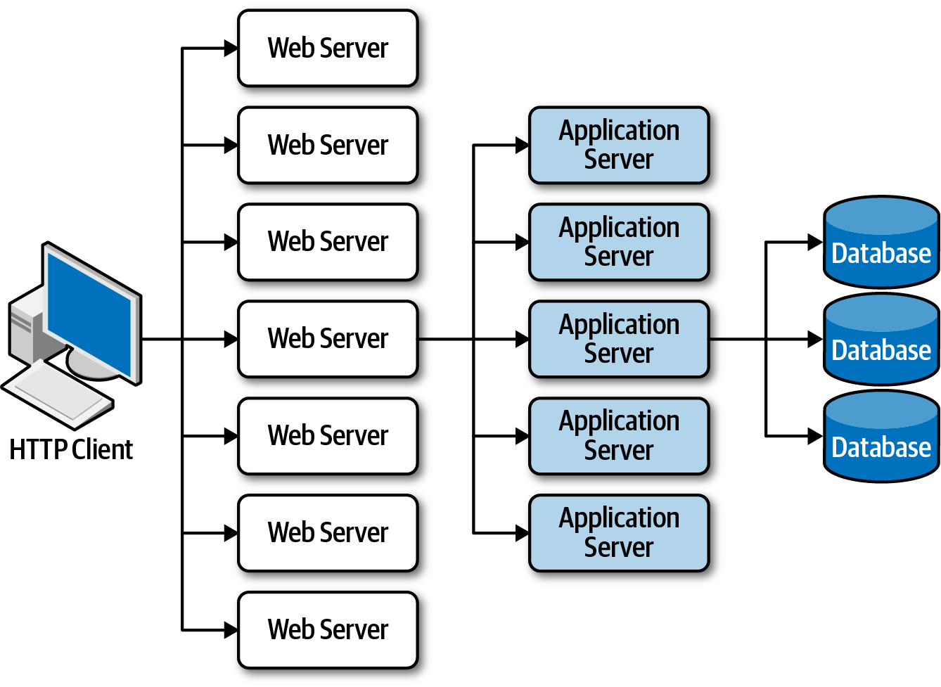
Scalability limits within a traditional web-based topology from Fundamentals of Software Architecture.
General Topology
Space-based architecture is rooted in the concept of tuple space, utilizing multiple parallel processors communicating through shared memory. It achieves high scalability, elasticity, and performance by eliminating the central database as a synchronous constraint. Instead, it relies on replicated in-memory data grids.
Tuple Space
A tuple space is an implementation of the associative memory paradigm for parallel/distributed computing. It provides a repository of tuples that can be accessed concurrently. As an illustrative example, consider that there are a group of processors that produce pieces of data and a group of processors that use the data. Producers post their data as tuples in the space, and the consumers then retrieve data from the space that match a certain pattern. This is also known as the blackboard metaphor. Tuple space may be thought as a form of distributed shared memory. Wikipedia link
Application data is stored in-memory and replicated across all active processing units. When a unit updates data, it asynchronously sends it to the database via messaging with persistent queues. Processing units dynamically start and shut down based on user load, addressing variable scalability. With no central database bottleneck, near-infinite scalability is achieved.
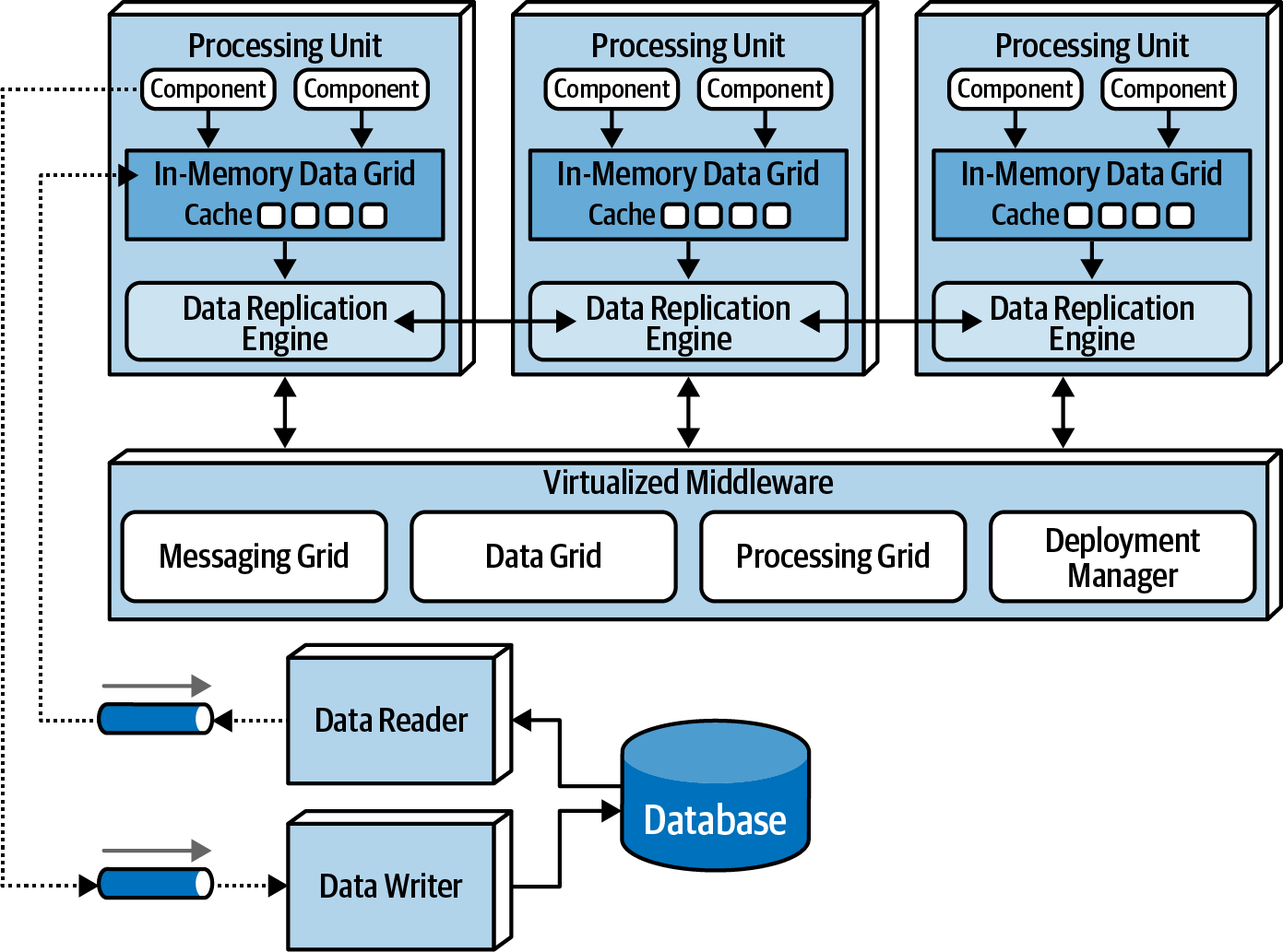
Key components include processing units with application code, virtualized middleware for unit management, data pumps for asynchronous data updates to the database, data writers for database updates, and data readers delivering database data to processing units on startup.
Processing Unit
The processing unit (as shown in the example image), encompasses the application logic, both web-based components and backend business logic. Its content varies depending on the application type. Smaller web-based apps might reside in a single processing unit, while larger ones may distribute functionality across multiple units based on application areas. The processing unit may also host small, single-purpose services (akin to microservices). Alongside the application logic, it integrates an in-memory data grid and replication engine, often implemented using products like Hazelcast, Apache Ignite, or Oracle Coherence.
Virtualized Middleware
The virtualized middleware manages architecture infrastructure, overseeing data synchronization and request handling. It comprises components like a messaging grid, data grid, processing grid, and deployment manager.
Messaging Grid
The messaging grid oversees input requests and session state. Upon receiving a request, it identifies available processing units and directs the request to one of them. The complexity can range depending on the algorithm used from simple round-robin to next-available, managed by a web server with load-balancing capabilities (e.g., HA Proxy, Nginx).
Data Grid
The data grid stands out as a pivotal component in this architecture style. In modern implementations, it resides within processing units as a replicated cache. However, when setups requiring an external controller or using a distributed cache, this functionality extends to both processing units and the virtualized middleware's data grid component. As the messaging grid can route requests to any available processing unit, maintaining identical data in each unit's in-memory grid is crucial. Despite the synchronous data replication illustration below, actual synchronization is asynchronous and rapid, typically finishing in under 100 milliseconds.
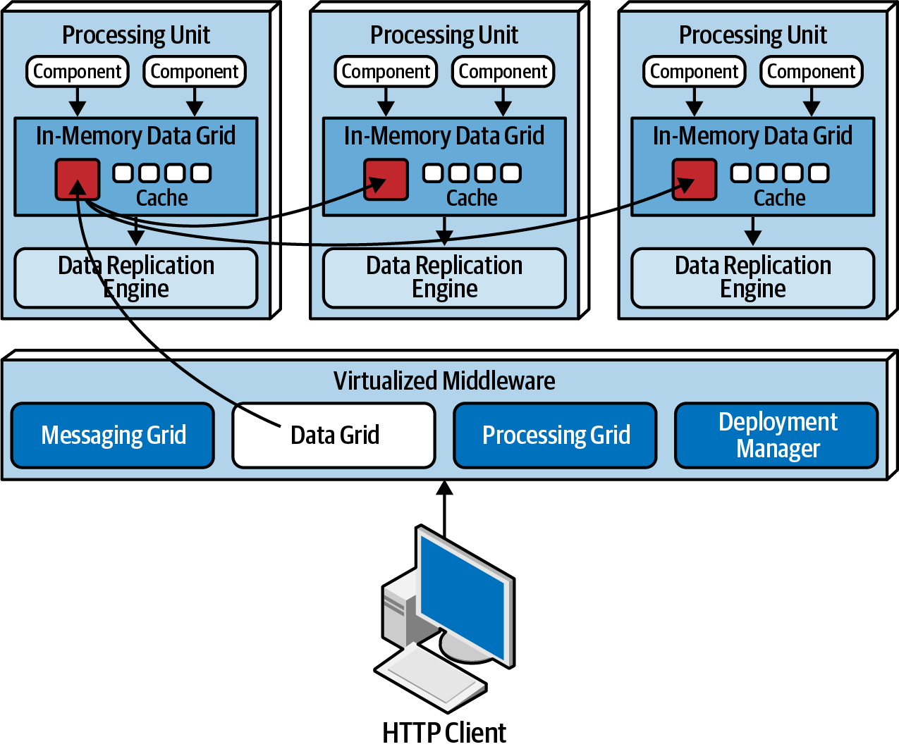
Data grid from Fundamentals of Software Architecture.
Data synchronization occurs among processing units that share the same named data grid. For instance, consider an internal replicated data grid in processing units containing customer profile information, using Hazelcast. Changes made to the CustomerProfile named cache in any processing unit replicate to all others with the same named cache. Each processing unit can hold multiple replicated caches as needed or request data from another unit (choreography) or leverage the processing grid for orchestration.
Data replication within processing units enables service instances to start and stop without requiring data retrieval from the database, as long as one instance holds the named replicated cache. When a processing unit instance starts, it connects to the cache provider (like Hazelcast), requests the named cache, and loads it from another instance.
Each processing unit is aware of all others (including themselves) through a member list, containing the IP addresses and ports of units using the same named cache. Suppose instance 1 receives a request to update customer profile information; when it updates the cache, the data grid (e.g., Hazelcast) asynchronously updates other replicated caches, ensuring consistent synchronization. If processing unit instances go down, all others are automatically updated to reflect the lost member.
Processing Grid
The processing grid, an optional element in virtualized middleware, oversees coordinated request processing when multiple processing units are involved in a single business request. If a request necessitates coordination between different processing unit types (e.g., an order processing unit and a payment processing unit), the processing grid mediates and orchestrates the request between these units.
Deployment Manager
The deployment manager component oversees the dynamic startup and shutdown of processing unit instances based on load conditions. Continually monitoring response times and user loads, it starts up new processing units with increased load and shuts down units during decreased load. This critical component ensures variable scalability (elasticity) within an application.
Data Pumps
A data pump is a vital component in space-based architecture, facilitating the transfer of data to another processor for database updates. Within this architecture, processing units don't directly interact with databases, making data pumps crucial. Asynchronous by nature, data pumps ensure eventual consistency between the in-memory cache and the database. When a processing unit updates its cache, it takes ownership of the update and uses the data pump to transmit the update to the database eventually.
Implemented through messaging, data pumps offer guaranteed delivery and preservation of message order through FIFO queueing. This decoupling between the processing unit and the data writer ensures uninterrupted processing, even if the data writer is temporarily unavailable.
Typically, there are multiple data pumps, each dedicated to a specific domain or subdomain (e.g., customer or inventory). They can be associated with specific caches (e.g., CustomerProfile, CustomerWishlist) or broader processing unit domains (e.g., Customer) with more extensive and general caches.
Data pumps adhere to contracts, defining actions (add, delete, update) associated with contract data. These contracts may take the form of JSON or XML schemas, objects, or value-driven messages. For updates, the data pump message usually contains only the new data values, such as the updated phone number and customer ID, along with an action to perform the update.
Data Writers
The data writer component plays a crucial role by receiving messages from a data pump and utilizing the information within these messages to update the database. Data writers can take the form of services, applications, or data hubs like Ab Initio. The scope of data writers varies based on the extent of the associated data pumps and processing units.
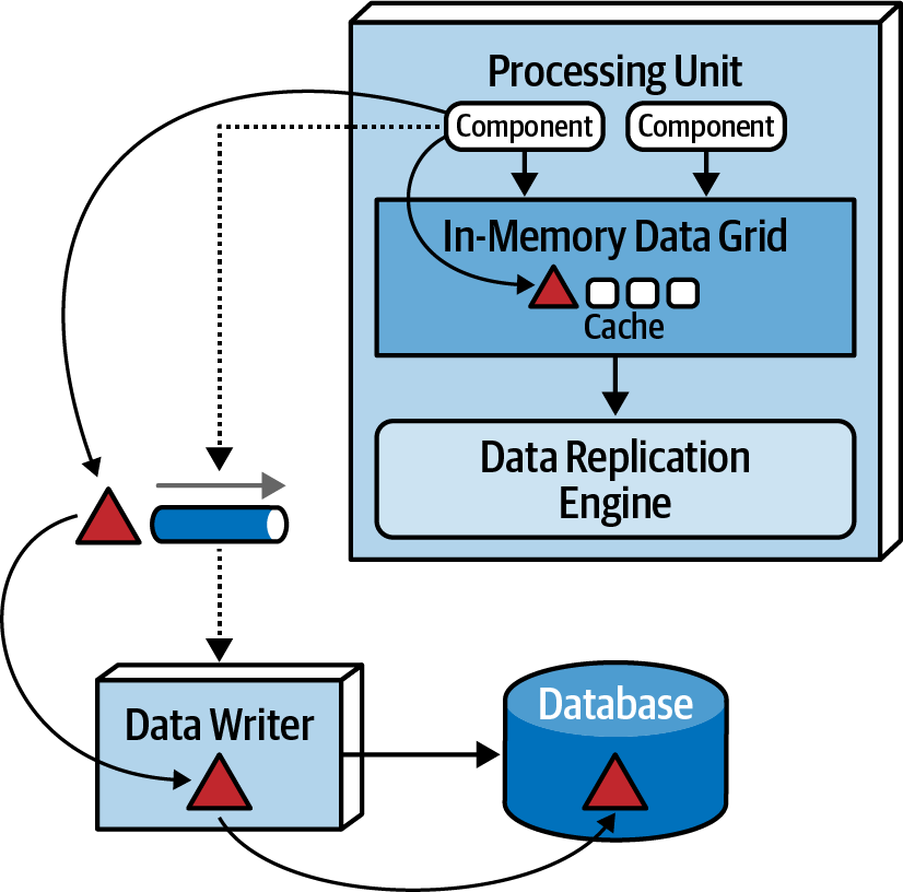
A domain-based data writer encapsulates the required database logic to manage updates within a specific domain, such as customer information, irrespective of the number of data pumps it handles.
Example
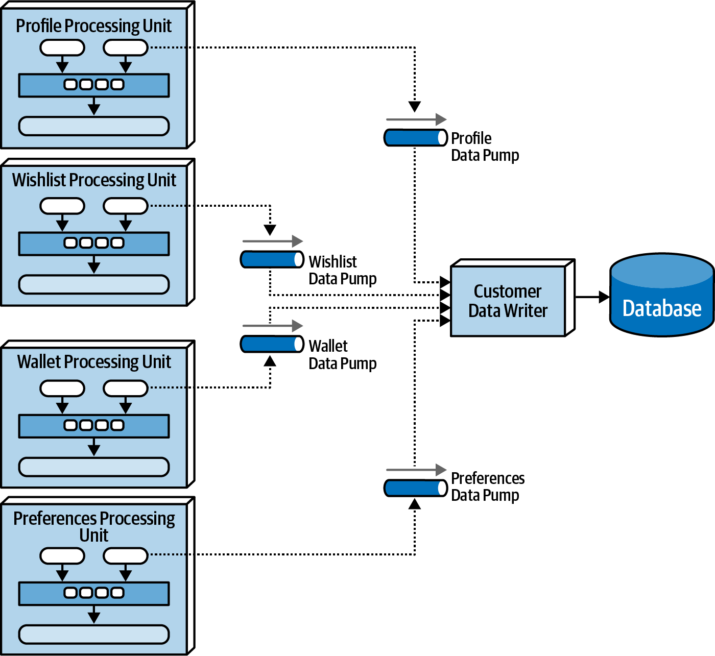
Domain-based data writer from Fundamentals of Software Architecture.
Dedicated data writers for each data pump from Fundamentals of Software Architecture.
Data Readers
Data readers take on the responsibility for reading data from the database and transmitting it to processing units through a reverse data pump. Their activation is limited to specific scenarios:
- Crash of all processing unit instances of the same named cache.
- Redeployment of all processing units within the same named cache.
- Retrieving archive data not contained in the replicated cache.
When all instances go down, indicating a system-wide crash or redeployment, data must be read from the database, a practice typically avoided in space-based architecture.
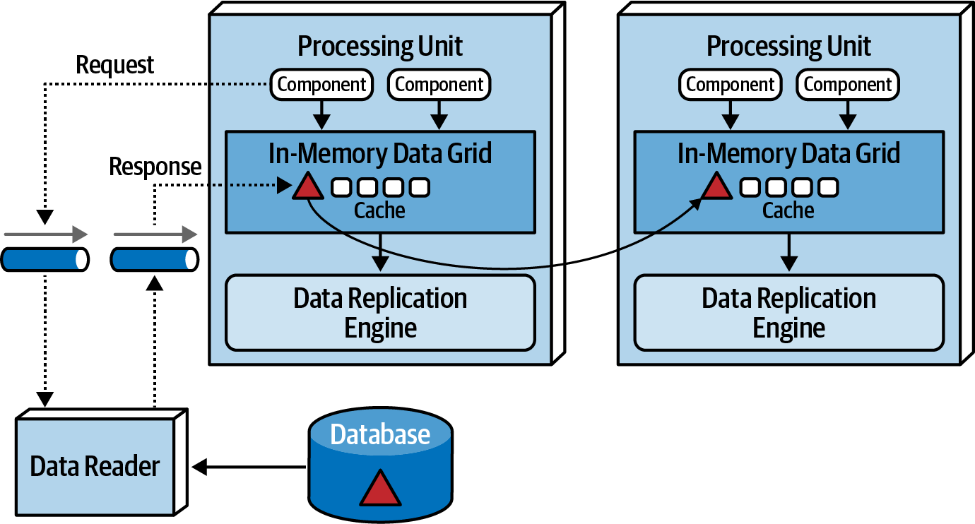
When instances of a class of processing unit start coming up, they attempt to gain a lock on the cache, the first successful instance becomes the temporary cache owner, initiating a message to a queue requesting data, while the others go into a wait state until the lock is released. The data reader, upon receiving the read request, executes the necessary database query logic to retrieve the required data. As the data reader queries data, it sends the results to a different queue known as a reverse data pump. The temporary cache owner processing unit loads the cache with the received data. After loading all the data, the temporary owner releases the lock, synchronizing all other instances, allowing processing to commence.
Similar to data writers, data readers can be domain-based or dedicated to a specific class of processing unit. Their implementation can take the form of services, applications, or data hubs.
Together, data writers and data readers form a data abstraction layer, ensuring processing units are decoupled from the underlying database table structures. In space-based architecture, a data abstraction layer allows incremental changes to the database without directly impacting the processing units.
Data Collisions
Data collisions in space-based architecture with replicated caching can arise when updates occur concurrently in service instances containing the same named cache,due to replication latency. Data updates made locally in one cache instance may be overridden by simultaneous updates from another cache instance during replication.
Example
To illustrate this issue, consider two service instances (Service A and Service B) with a replicated cache of product inventory:
- Initial inventory count for
product Z is 500 units. Service A updatesthe inventory cache for product Z to 490 units (10 sold).Simultaneously, during replication,Service B updatesthe inventory cache for product Z to 495 units (5 sold).Due to replication, the Service B cache is updated to 490 units, reflecting the Service A update.- Similarly, the
Service A cache is updated to 495 units, reflecting the Service B update. Both caches in Service A and B are now incorrect and out of sync(inventory should be 485 units).
Calculating Probability to Data Collisions
Calculating the probability of data collisions involves considering factors. The formula used to estimate the likelihood of potential data collisions incorporates these factors:
Formula
Collision Rate = N*(UR²/S)*RL
Where:
- N = number of service instances using the same named cache.
- UR = update rate in milliseconds (squared).
- S = cache size (in terms of number of rows)
- RL = replication latency
Base Example
Collision Rate = N*(UR²/S)*RL
- N = 5
- UR = 20 updates/second
- S = 50.000 rows
- RL = 100 milliseconds = 0.1 seconds
Collision Rate = 5 * (20²/50.000) * 0.1
Collision Rate = 5 * (400/50.000) * 0.1
Collision Rate = 5 * 0.008 * 0.1
Collision Rate = 0.004 per second
Updates per minute = 20 * 60 = 1200
Updates per hour = 1200 * 60 = 72000
Collision Rate per hour = 0.004 * 3600
Collision Rate per hour = 14.4
Percentage = 14.4 / 72000 * 100
Percentage = 0.02%
The formula provided is a valuable tool for assessing the likelihood of data collisions and determining the feasibility of using replicated caching in a space-based architecture. Replication latency, influenced by network type and physical distance between processing units, plays a crucial role in data consistency. While actual replication latency values are often not readily available and need to be measured in a production environment, a planning value of 100 milliseconds is commonly used when precise figures are unavailable.
Reducing Replication Latency
Changing the replication latency from 100 milliseconds to 1 millisecond yields the same number of updates (72,000 per hour) but produces only the probability of 0.1 collisions per hour.
Collision Rate = N*(UR²/S)*RL
- N = 5
- UR = 20 updates/second
- S = 50.000 rows
- RL = 1 milliseconds = 0.001 second
Collision Rate = 5 * (20²/50.000) * 0.001
Collision Rate = 5 * (400/50.000) * 0.001
Collision Rate = 5 * 0.008 * 0.001
Collision Rate = 0.00004 per second
Updates per minute = 20 * 60 = 1200
Updates per hour = 1200 * 60 = 72000
Collision Rate per hour = 0.00004 * 3600
Collision Rate per hour = 0.144
Percentage = 0.144 / 72000 * 100
Percentage = 0.0002%
The number of processing units sharing the same named cache (represented by the number of instances) has a direct proportional relationship with the potential number of data collisions.
Decreasing Processing Units
Reducing the number of processing units from 5 instances to 2 instances yields a data collision rate of only 6 per hour out of 72,000 updates per hour:
Collision Rate = N*(UR²/S)*RL
- N = 2
- UR = 20 updates/second
- S = 50.000 rows
- RL = 100 milliseconds = 0.1 seconds
Collision Rate = 2 * (20²/50.000) * 0.1
Collision Rate = 2 * (400/50.000) * 0.1
Collision Rate = 2 * 0.008 * 0.1
Collision Rate = 0.0016 per second
Updates per minute = 20 * 60 = 1200
Updates per hour = 1200 * 60 = 72000
Collision Rate per hour = 0.0016 * 3600
Collision Rate per hour = 5.76
Percentage = 5.76 / 72000 * 100
Percentage = 0.008%
Cache size is inversely proportional to collision rates, meaning that as the cache size decreases, collision rates increase.
Smaller Cache Size
Reducing the cache size from 50,000 to 10,000 rows, while keeping other factors constant, increases the collision rate to 72 per hour, emphasizing the impact of cache size on collision probability.
Collision Rate = N(UR²/S)RL`
- N = 5
- UR = 20 updates/second
- S = 10.000 rows
- RL = 100 milliseconds = 0.1 seconds
Collision Rate = 5 * (20²/10.000) * 0.1
Collision Rate = 5 * (400/10.000) * 0.1
Collision Rate = 5 * 0.04 * 0.1
Collision Rate = 0.02 per second
Updates per minute = 20 * 60 = 1200
Updates per hour = 1200 * 60 = 72000
Collision Rate per hour = 0.02 * 3600
Collision Rate per hour = 72
Percentage = 72 / 72000 * 100
Percentage = 0.1%
In a typical scenario, systems don't maintain consistent update rates over extended periods. Therefore, when using this calculation, understanding the maximum update rate during peak usage and calculating minimum, normal, and peak collision rates can provide a more nuanced perspective.
Cloud vs On-Premises Implementations
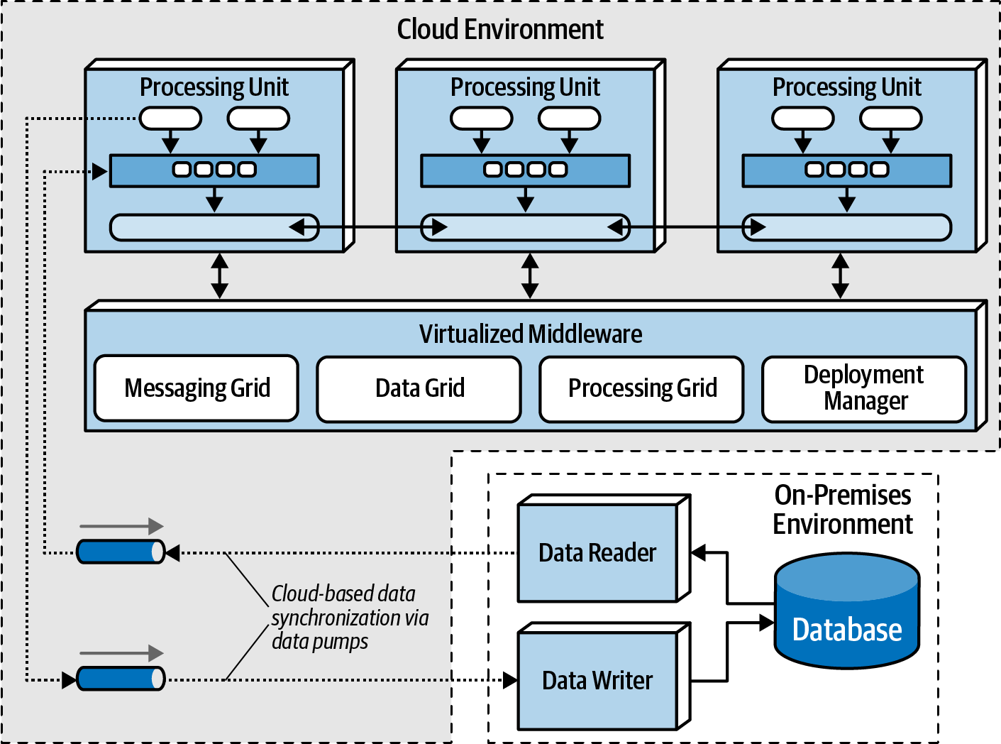
Space-based architecture provides versatile deployment options, allowing the entire system, including processing units, virtualized middleware, data pumps, data readers and writers, and the database, to be implemented either in on-premises environments or within cloud-based environments. Additionally, this architecture style offers a unique capability to deploy applications using processing units and virtualized middleware in managed cloud environments while retaining physical databases and associated data on-premises.
A key strength of this architecture lies in the possibility of deploying applications through processing units and virtualized middleware in managed cloud-based environments while maintaining physical databases and associated data on-premises. This configuration facilitates highly efficient cloud-based data synchronization, leveraging asynchronous data pumps and the eventual consistency model inherent in this architecture. The setup allows for transactional processing in dynamic and elastic cloud-based environments while upholding the management of physical data, reporting, and data analytics securely within the local and on-premises environments.
Replicated vs Distributed Caching
Space-based architecture heavily relies on caching to facilitate the transactional processing of an application. While the predominant caching model is replicated caching, space-based architecture can also leverage distributed caching.
In replicated caching, each processing unit possesses its in-memory data grid synchronized among all units using the same named cache. This method is not only exceptionally fast but also offers robust fault tolerance, as there's no central server acting as a single point of failure.
About Replicate Cache and Single Point of Failure
Some exceptions may exist based on the caching product's implementation, but the trend is moving away from relying on external controllers for replication.
Replicated caching is the standard for space-based architecture, but certain scenarios, such as high data volumes or update rates, may necessitate the use of distributed caching. Internal memory caches exceeding 100 MB can pose challenges for elasticity and scalability, and in situations with high update rates, distributed caching becomes a viable alternative. Furthermore, as shown in Data Collisions, in situations where the update rate of cache data becomes too high, and the data grid struggles to maintain consistency across all processing unit instances, distributed caching can be a viable solution.
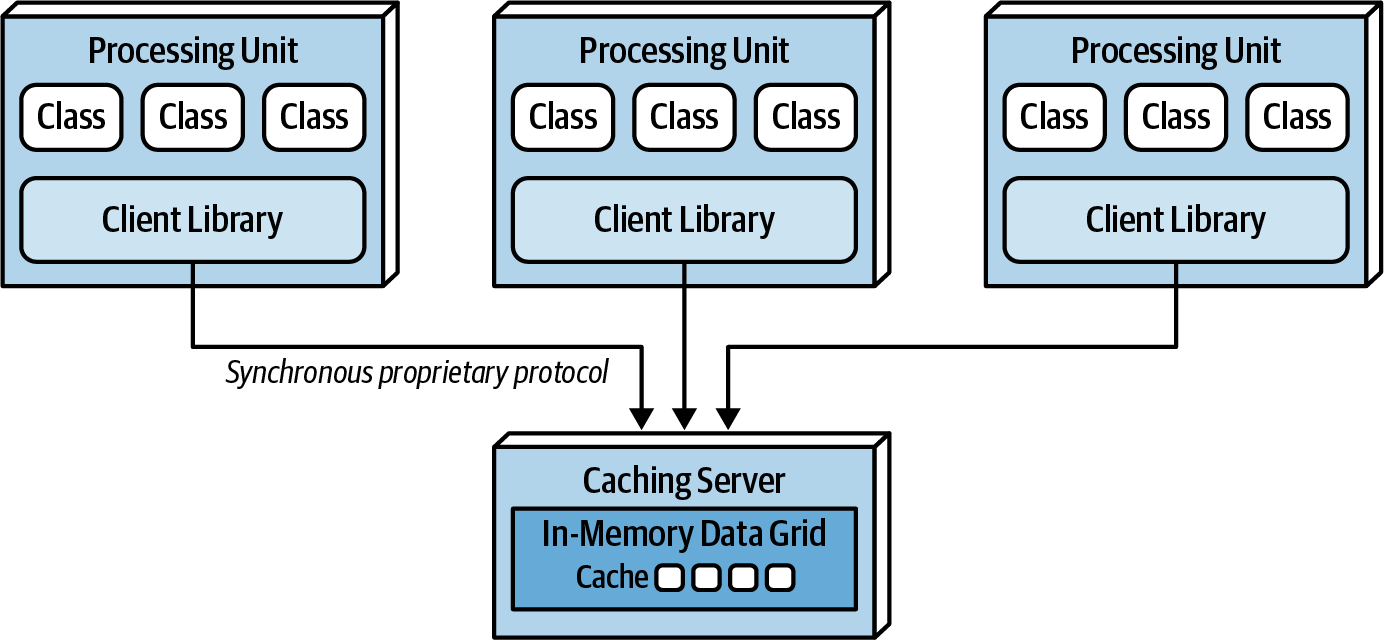
Distributed caching involves an external server or service dedicated to maintaining a centralized cache. Processing units access data from this central cache server through a proprietary protocol. While distributed caching ensures high data consistency due to the centralized nature of the data, it comes with performance trade-offs, as accessing cache data remotely adds latency to the system. Fault tolerance can be a concern, and mirroring the distributed cache is one approach to mitigate it, though it may introduce consistency issues.
Choosing between replicated and distributed caching depends on factors such as data consistency needs, performance considerations, and fault tolerance requirements. Distributed caching excels in maintaining highly consistent data, while replicated caching offers better performance and fault tolerance. Often, both models can be applicable within a single application context, allowing each to be leveraged based on its specific strengths. For instance, a distributed caching model may be suitable for maintaining consistently critical data like inventory counts, while a replicated cache may be chosen for performance and fault tolerance in managing less dynamic data like customer profiles.
| Decision criteria | Replicated cache | Distributed cache |
|---|---|---|
| Optimization | Performance | Consistency |
| Cache size | Small(<100MB) | Large(>500MB) |
| Type of data | Relatively static | Highly dynamic |
| Update frequency | Relatively low | High update rate |
| Fault tolerance | High | Low |
Implementation Examples
Space-based architecture proves effective for applications experiencing high spikes in user or request volume, especially those surpassing 10,000 concurrent users.
Concert Ticketing System
Concert ticketing systems face unique challenges, particularly during popular concert announcements when user volumes skyrocket from hundreds to potentially tens of thousands. Constantly accessing a central database synchronously in such systems would likely not work. The sheer volume of tens of thousands of concurrent requests, coupled with the rapid update frequency, makes it exceedingly difficult for a standard database to handle through conventional synchronous transactions at this scale.The architecture's high elasticity is crucial for handling these sudden spikes.
Space-based architecture allows instant recognition of increased user demand, prompting the deployment manager to initiate numerous processing units to efficiently manage the surge. Configuring the deployment manager to start these instances right before ticket sales ensures optimal performance.
Online Auction System
Online auction systems share similarities with concert ticketing in terms of high performance and elasticity demands, coupled with unpredictable user and request spikes. Space-based architecture excels in this context by allowing the dynamic creation and destruction of processing units based on changing load conditions. Dedicated processing units for each auction ensure data consistency, and the asynchronous nature of data pumps facilitates swift transmission of bidding data to various processing units, enhancing overall bidding process performance.